1. manual reversing
1. set the remote control box’s “output switch” to “off”, set the “positive regulation” “reverse regulation” to the minimum; set the “work state” to “(CC–constant current)” or (CV–constant voltage) as your needs.
2. set the “reverse mode” to “manual” ,if set the “manual positive” ,put the “output switch” to “on”,adjust the timer’s “positive regulation”,then the rectifier output the positive voltage/current as your needs; set the “manual reversing” , set the “output switch” to “ON”, adjust “reverse regulation” ,the rectifier output the reverse voltage/current as your needs
Note. Under “manual mode”,If change “manual positive” to “manual reverse”; or change “manual reverse” to “manual positive” ,before change,first set “output switch” to “off” ,then change “manual positive” to “manual reverse”; or change “manual reverse” to “manual positive” as your needs,then set “output switch ” to “open”.
2. Automatic reverse
Step 1. set positive and reverse working current or voltage ( finished the setting under the manual mode).
Step 2. set the “output switch” to “off”
Step 3. change the “reverse mode ” to “automatic”,the LED light,the rectifier enter into standby,then set the total working time “J0”,set positive working time “J1”, convert time “J2”=1s,set reverse time“ J3”,set convert time “J4” =1s .
Step 4. set “output switch” to “ON”,press “start”,the rectifier enter into the set work program,then finished the program,the rectifier shut down automatically with the sound of alarm.
Step 5. press the “reset” ,the alarm will stop,the timer enter standby. If you want the rectifier run again,just press “start”
Note: If just want only positive work, set the timer “J0”= “J1” “J2” “J3” “J4”=0
If just want only reverse work, set the timer “J0”= “J3” “J1” “J2” “J4”=0
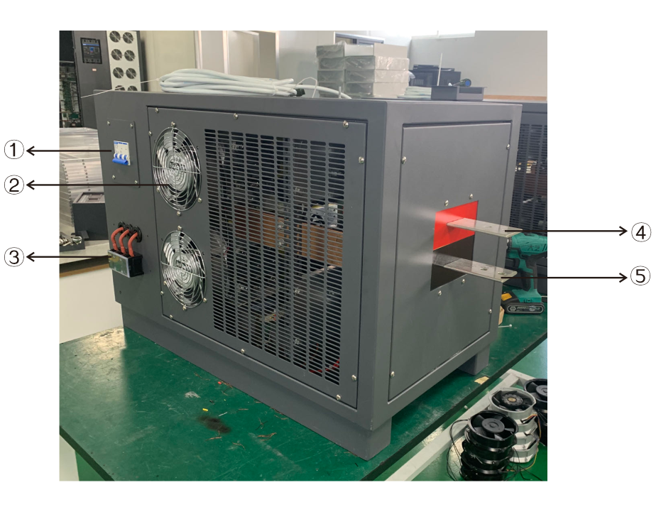
| 1. AC breaker | 2. DC fan |
| 3. AC input 380V 3 phase | 4. Positive copper bus bar |
| 5. Negative copper bus bar |
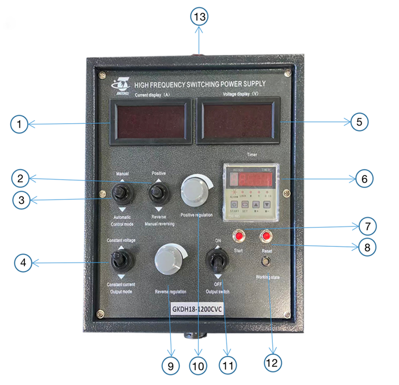
| 1. Digital Ammeter: display the output current | 2. Positive/Reverse Manual reversing |
| 3. Manual/Automatic Control mode switching | 4. CC/CV switch: constant voltage/constant current convert switch |
| 5. Digital voltmeter: display the output voltage | 6. Timer |
| 7. Start | 8. Reset |
| 9. Output Reverse regulation: output adjustment | 10. Output Positive regulation: output adjustment |
| 11. Output ON/OFF | 12. Working state |
| 13. Indicator light |
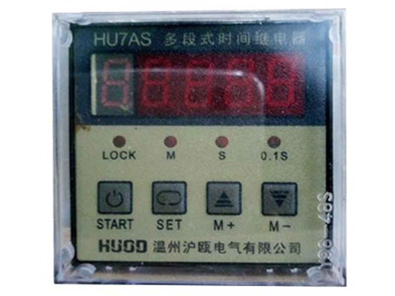
Instruction for the Multi-timer
Display:
0=J0=TOTAL WORK TIME
1=J1
2=J2
3=J3
4=J4
Total time 0:
Step 1: Press twice SET
Step 2: Press M+ or M- to change time u need.
Step 3: Press START to choose unit (M/S/0.1S)
Finished total time(J0) steps, please continue to finish steps followed.
Positive Time 1
Step 1: Press SET ( only one time),
Step 2: Press M+ or M- to change time u need.
Step 3: Press START to choose unit (M/S/0.1S)
Finished positive time steps, please continue to finish steps followed.
2
Step 1: Press SET ( only one time),
Step 2: Please set J2 to be 1s or 2s
Step 3: Press START
3
Reversing Time
Step 1: Press SET ( only one time),
Step 2: Press M+ or M- to change time u need.
Step 3: Press START to choose unit (M/S/0.1S)
Finished reverse time steps, please continue to finish steps followed.
4
Step 1: Press SET ( only one time),
Step 2: Please set J4 to be 1s or 2s
Step 3: Press START
Finally, Press SET to save all steps. Then press START. Timer will start to work.
PS:
1. Repeat working mode: J0 time>J1+J2+J3+J4 time. Timer will repeat to work until Total time is up. Then press RESET (this button is on panel of rectifier)
Single working mode: J0=J1+J2+J3+J4. Timer only works one time. When time is up., please press RESET (this button is on panel of rectifier)
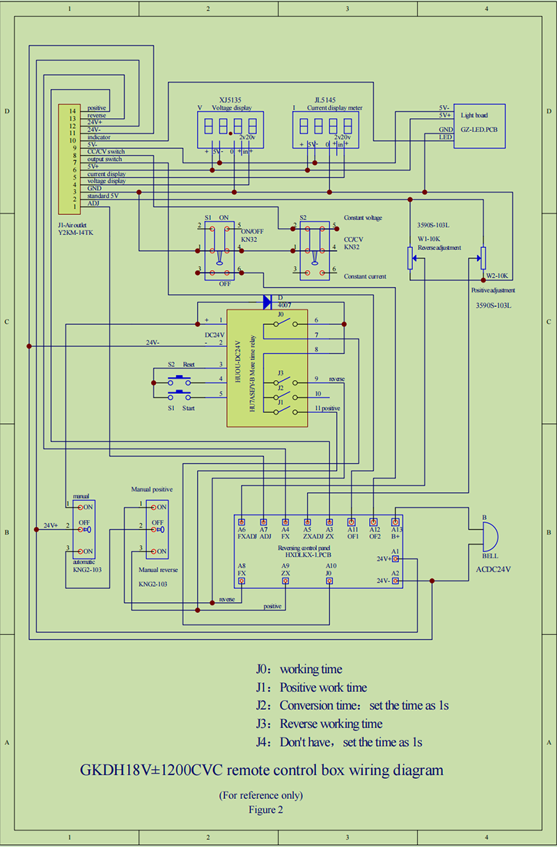
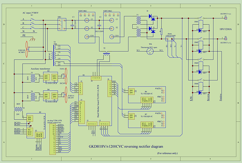
The diagram is as below:
Post time: Dec-07-2023


