
1.What is PCB Electroplating?
PCB electroplating refers to the process of depositing a layer of metal onto the surface of a PCB to achieve electrical connection, signal transmission, heat dissipation, and other functions. Traditional DC electroplating suffers from issues such as poor coating uniformity, insufficient plating depth, and edge effects, making it difficult to meet the manufacturing demands of advanced PCBs like High-Density Interconnect (HDI) boards and Flexible Printed Circuits (FPC). High-frequency switching power supplies convert mains AC power to high-frequency AC, which is then rectified and filtered to produce stable DC or pulsed current. Their operating frequencies can reach tens or even hundreds of kilohertz, far exceeding the power frequency (50/60Hz) of traditional DC power supplies. This high-frequency characteristic brings several advantages to PCB electroplating.
2.Advantages of High-Frequency Switching Power Supplies in PCB Electroplating
Improved Coating Uniformity: The "skin effect" of high-frequency currents causes the current to concentrate on the surface of the conductor, effectively improving coating uniformity and reducing edge effects. This is particularly useful for plating complex structures like fine lines and micro-holes.
Enhanced Deep Plating Capability: High-frequency currents can better penetrate hole walls, increasing the thickness and uniformity of plating inside holes, which meets the plating requirements for high aspect ratio vias.
Increased Electroplating Efficiency: The fast response characteristics of high-frequency switching power supplies enable more precise current control, reducing plating time and increasing production efficiency.
Reduced Energy Consumption: High-frequency switching power supplies have high conversion efficiency and low energy consumption, aligning with the trend of green manufacturing.
Pulse Plating Capability: High-frequency switching power supplies can easily output pulsed current, enabling pulse electroplating. Pulse plating improves coating quality, increases coating density, reduces porosity, and minimizes the use of additives.
3.Examples of High-Frequency Switching Power Supply Applications in PCB Electroplating
A. Copper Plating: Copper electroplating is used in PCB manufacturing to form the conductive layer of the circuit. High-frequency switching rectifiers provide precise current density, ensuring uniform copper layer deposition and improving the quality and performance of the plated layer.
B. Surface Treatment: Surface treatments of PCBs, such as gold or silver plating, also require stable DC power. High-frequency switching rectifiers can provide the correct current and voltage for different plating metals, ensuring smoothness and corrosion resistance of the coating.
C. Chemical Plating: chemical plating is carried out without current, but the process has strict requirements for temperature and current density. High-frequency switching rectifiers can provide auxiliary power for this process, helping to control plating rates.
4.How to Determine PCB Electroplating Power Supply Specifications
The specifications of the DC power supply required for PCB electroplating depend on several factors, including the type of electroplating process, PCB size, plating area, current density requirements, and production efficiency. Below are some key parameters and common power supply specifications:
A.Current Specifications
●Current Density: The current density for PCB electroplating typically ranges from 1-10 A/dm² (ampere per square decimeter), depending on the electroplating process (e.g., copper plating, gold plating, nickel plating) and coating requirements.
●Total Current Requirement: The total current requirement is calculated based on the PCB's area and current density. For example:
⬛If the PCB plating area is 10 dm² and the current density is 2 A/dm², the total current requirement would be 20 A.
⬛For large PCBs or mass production, several hundred amperes or even higher current outputs may be required.
Common Current Ranges:
●Small PCBs or laboratory use: 10-50 A
●Medium-sized PCB production: 50-200 A
●Large PCBs or mass production: 200-1000 A or higher
B.Voltage Specifications
⬛PCB electroplating generally requires lower voltages, typically in the range of 5-24 V.
⬛Voltage requirements depend on factors such as the resistance of the plating bath, the distance between electrodes, and the conductivity of the electrolyte.
⬛For specialized processes (e.g., pulse plating), higher voltage ranges (such as 30-50 V) may be required.
Common Voltage Ranges:
●Standard DC electroplating: 6-12 V
●Pulse plating or specialized processes: 12-24 V or higher
Power Supply Types
●DC Power Supply: Used for traditional DC electroplating, providing stable current and voltage.
●Pulse Power Supply: Used for pulse electroplating, capable of outputting high-frequency pulsed currents to improve plating quality.
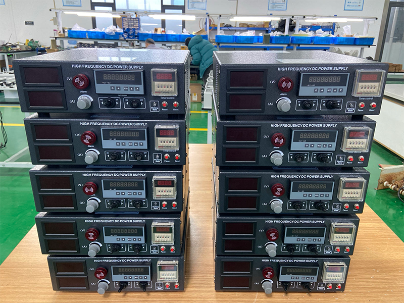
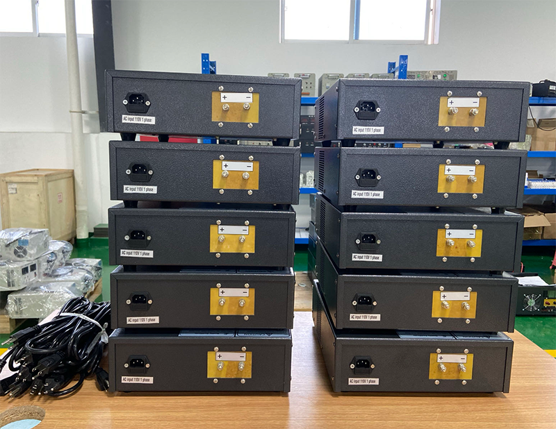
●High-Frequency Switching Power Supply: High efficiency and fast response, suitable for high-precision electroplating requirements.
C.Power Supply Power
The power supply power (P) is determined by the current (I) and voltage (V), with the formula: P = I × V.
For example, a power supply that outputs 100 A at 12 V would have a power of 1200 W (1.2 kW).
Common Power Range:
●Small equipment: 500 W - 2 kW
●Medium-sized equipment: 2 kW - 10 kW
●Large equipment: 10 kW - 50 kW or higher
Post time: Feb-13-2025


